Table of Contents
LoRa Measurement Nodes
Introduction
The Inform@Risk Measurement Node is the basis for all other sensors in the Inform@Risk measurement system. It is sometimes also referred to simply as 'Measurement Node'. In this document, the necessary materials and assembly of the basic Measurement Node are described. For more information about the PCB (Printed Circuit Board), please check the corresponding hardware documentation under www.informrisk.alpgeorisk.com. There, the circuit schematics are shared as PDF and Fritzing project files.
Essentially, the assembly of the Measurement Node consists of installing the PCB in an enclosure, preparing the power supply and, optionally, installing the inclination board.
Materials
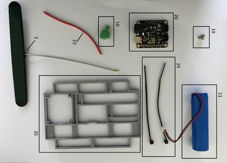
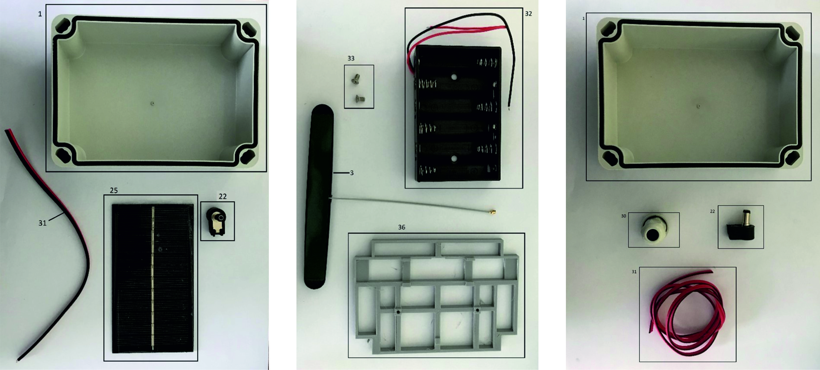
The materials needed for the construction and installation of the Measurement Node are displayed in figures \ref{fig:mat1} and \ref{fig:mat2} and listed in tables \ref{tab:mat_gen}, \ref{tab:mat_sol} and \ref{tab:mat_bat}. The numbers in the tables correspond to those of the images. Detailed material lists and approximate costs can be found on the website \todo{add link}.
Necessary tools are a wire cutter, a set of screwdrivers, a soldering iron as well as a wire stripper.
Table 1: General material list for the Measurement Node.
| Nr. | Amount | Description |
|---|---|---|
| 1 | 1 | Enclosure - IP66, 130 x 94 x 81 mm |
| 2 | 1 | Wall Bracket (optional) |
| 3 | 1 | LoRa Antenna |
| 4 | 1 | Cylinder head screws M3x35 |
| 5 | 8 | M3 Nuts |
| 6 | 7 | Cylinder screws DIN 84 M3x6, galvanized |
| 7 | 4 | Cylinder head screws M2x5 |
| 8 | 1 | PCB for inclination board (Murata CL 3300) |
| 9 | 1 | Inform@Risk Measurement Node PCB |
| 10 | 2 | 2-pole Board connector |
| 11 | 1 | 6-pole Board connector |
| 12 | 1 | 4-pole Board connector |
| 13 | 1 | Arduino MKR WAN 1310 |
| 14 | 4 | Washer PCB/Metal (1-2 mm) |
| 15 | 4 | Screws for PCB, galvanized, 3.5*9.5 |
| 16 | 4 | Cable gland (3.5-6 mm) |
| 17 | 1 | Silica package |
| 18 | 1 | Circular level |
| 37 | 1 | PCB holder for inclination board |
Table 2: Additional material list for solar powered version.
| Nr. | Amount | Description |
|---|---|---|
| 19 | 1 | Screws, lens head M2x5 |
| 20 | 1 | Charge controller board |
| 21 | 1 | LiPo battery |
| 22 | 1 | Angle plug |
| 23 | 1 | Wire 2*0.14mm2, about 15-20 cm |
| 24 | 2 | Cable ties |
| 25 | 1 | Solar panel (on enclosure) |
| 26 | 1 | Epoxy resin adhesive |
| 27 | 1 | Solar panel (external) |
| 28 | 4 | Special screws for external solar panel |
| 29 | 1 | Base plate for external solar panel |
| 30 | 1 | Cable gland (3.5-6 mm) |
| 31 | 1 | Wire 2*0.14mm2, about 15-20 cm |
| 35 | 1 | Lid-Mount for solar |
Table 3: Additional material list for battery powered version.
| Nr. | Amount | Description |
|---|---|---|
| 32 | 1 | 6AA-battery-holder |
| 33 | 2 | Screws, countersunk head M3x5 |
| 34 | 6 | AA battery |
| 36 | 1 | Lid-Mount for battery |
Assembly
In this section, the assembly of the Measurement Node is explained in detail. It can be performed easily in a small workshop by one person. We estimate the work time with about 20-30 minutes per node, if multiple nodes are assembled in one session.
The three different versions are a battery powered version, a solar powered version with internal solar panel and one with external solar panel. The latter two are based on the same materials and preparation and differ mainly in the location of the solar panel. Since the power supply is located in the lid, only this part of the enclosure differs between the three versions. The PCB preparation and generally the lower part of the enclosure is always the same and explained in the first section below.
Preparation of the PCB and bottom part
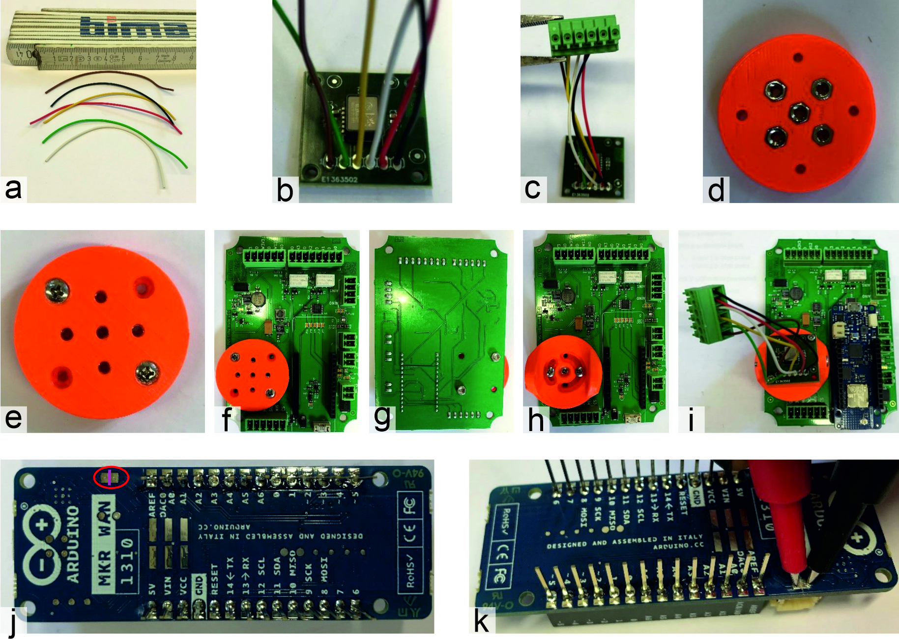
The necessary steps to prepare the bottom part of the enclosure are displayed in figure \ref{fig:bot} and explained in the following paragraph. The numbers in brackets correspond to those in the tables in the materials chapter.
- Prepare six single wires in 8 cm length and strip the wire at both ends for about 2-3 mm (figure \ref{fig:bot}a). Ideally, the wires should be of six different colors in order to differentiate them more easily.
- Solder the wires to the inclination board (8) in the order pictured (figure \ref{fig:bot}b). Note that the wires should be soldered perpendicular to the board, so the wires can reach to the main PCB more easily. The other ends of the wires get screwed into the 6-port connector (11, figure \ref{fig:bot}c).
- To mount the board onto the main PCB (9), 3D prints have been developed. The bottom part is first fitted with nuts (5) on the underside (figure \ref{fig:bot}d), then two screws (6) are drilled through the holes from the other side (figure \ref{fig:bot}e). They should look out on the bottom side for some millimetres.
- The mount can now be attached to the main PCB (9) using two nuts on the underside of the PCB (figure \ref{fig:bot}f, g). Then, the top part of the 3D printed part can be put on top and fixed with two more M3x6 screws (6, figure \ref{fig:bot}h).
- The inclination board (8), which has been screwed onto the inclination board holder (37) with four M2x5 screws (7), can then be installed on the mount using a long cylinder head screw (4, figure \ref{fig:bot}i) and nut. The 6-port connector can then be plugged onto the main PCB (bottom in figure \ref{fig:bot}i).
- The Arduino board (13) can be inserted directly onto the circuit board, but before that, one connection on it has to be cut with a trimming knife. Between the two pads on the top left in figure \ref{fig:bot}j (red circle), make a cut so the connection is severed (violet line). Check that there is no connection anymore using a multimeter (figure \ref{fig:bot}k).
- Screw PCB onto enclosure bottom using nuts and washers (1-2~mm height).
Preparation of the Lid
Solar Powered
The solar powered design consists, first, of the solar panel and second, the charge controller, mount and accessories. There are two versions of the solar powered design, one with internal solar panel on the enclosure and one with an external solar panel which is connected through a cable gland in the enclosure. In the following, the part that is universal (charge controller, mount and accessories) is described, followed by two parts which are dependent on the solar panel versions.
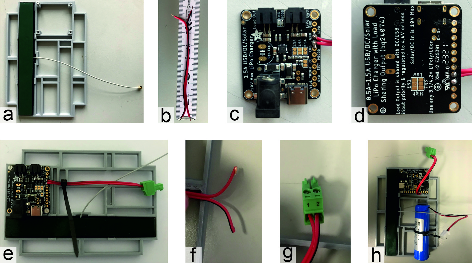
- Cut off the plastic ends of the LoRa antenna (3) and snap it onto the solar Lid-Mount (35) with the antenna cable looking inwards (figure \ref{fig:sol}a).
- Prepare a double wire of 20 cm length (23) with about 2 mm of wire stripped at both ends (figure \ref{fig:sol}b).
- Solder this wire onto the charge controller board (20): Black wire to 'GND', red wire to 'Out' (figure \ref{fig:sol}c, d).
- Screw charge controller board (20) onto 3D-printed mount (35) using two M2 screws (19) and fix the wire with cable ties (24, figure \ref{fig:sol}e).
- Kink other sides of the wire (23) and put the ends in the 2-pole board connector (10) - red in 1 and black in 2 - and screw the connector (figure \ref{fig:sol}f, g).
- Add LiPo battery (21) with cable ties (24) to the mount (35) and plug into charge controller board in port 'Batt' (figure \ref{fig:sol}h).
Internal Solar Panel
The version with internal solar panel is manufactured with the following steps:
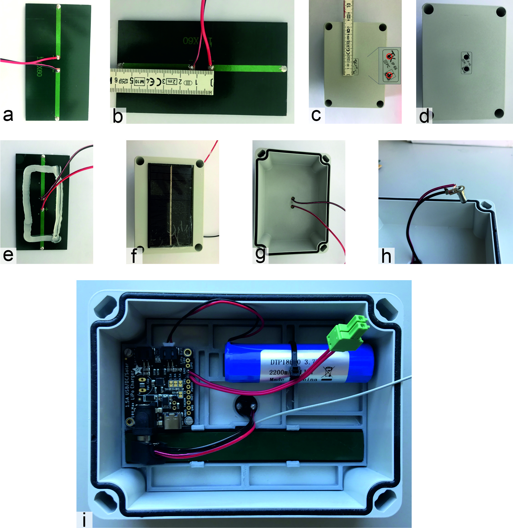
- Solder the wire (31) onto the solar panel (25), red wire to +, black wire to - (figure \ref{fig:sol2}a).
- Drill two holes in the middle of the lid (1) with 1.5~cm distance (figure \ref{fig:sol2}b, c, d), then round off the holes with a deburrer.
- Lead the cables of the solar panel through the holes and glue the solar panel onto the enclosure (figure \ref{fig:sol2}e, f, g).
- Cut the wires to about 8~cm length and strip the wires for some milimeters (cut black wire about 3~mm shorter than red). Solder these wires onto the angle plug (22) by soldering the red wire to the inner ring and black wire to the metal plate (figure \ref{fig:sol2}h).
- Attach the prepared solar lid-mount (35) in the enclosure and glue it onto it. The angle plug can then be attached to the charge controller board (figure \ref{fig:sol2}i).
External Solar Panel
For the version with external solar panel (not attached to enclosure), the construction is easier: simply attach one side of a wire (31) to the angle plug (22) and the other side to a luster terminal with two poles. On the enclosure lid, add a cable gland through which the wire from the solar panel is routed and plugged to the other side of the luster terminal.
- Drill a hole with 12.5~mm diameter on the short side of the lid (figure \ref{fig:extsolar}a).
- Add the cable gland (figure \ref{fig:extsolar}b).
- Solder the wire to the angle plug inside the enclosure and plug it into the charge controller (figure \ref{fig:extsolar}c, d, e).
- Either leave the rest of the wire hanging out of the enclosure or cut it inside the enclosure and add a luster terminal to which the wire from the solar panel can be attached later.
Battery Powered
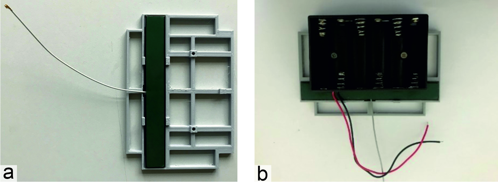
The construction of the battery powered design is relatively simple, as it only consists of a couple of parts. The steps are explained below and displayed in figure \ref{fig:batt}.
- Same as above, cut off the plastic ends of the LoRa antenna (3) and snap it onto the battery Lid-Mount (36) with the antenna cable looking inwards (figure \ref{fig:batt}a).
- Attach the 6AA battery holder (32) with two countersunk screws M3x5 (33) to the mount (figure \ref{fig:batt}b).
- Kink the ends of the wires of the battery holder (32) and put the ends in the 2-pole board connector (10) - red in 1 and black in 2 - and screw them in the connector.
Function Test
Finally, the basic function of the measurement node can be tested. The function in detail can be tested with the next document (2 - Measurement Node Software Installation).
- Set up the multimeter to check dc voltage
- To check the battery voltage, check the voltage between the battery + and - pins. It should be above 3.5~volts (figure \ref{fig:func}a, b).
- To check if the solar panel works, it can be put beneath a bright light. Then, check the voltage between the two pins of the angle plug. It should be above 6~volts (figure \ref{fig:func}c, d).
- When this is ok, you can plug it in again and check the voltage on the 2-pole board connector (10) - this should be around 3.8-4~V (figure \ref{fig:func}e).
- When all these tests check out ok, you can glue everything to the enclosure and, in case of the internal solar panel, fill the holes with epoxy resin adhesive.
Installation
The installation process of the infrastructure nodes consists of anchoring the node to a firm wall or column, preferably brick and concrete structures. The more rigid and firm the structures it is installed on are, the more accurate the data is in relation to ground movements.
The tools necessary for the installation of the infrastructure nodes are: hammer drill, wall drill, wall drill bit, screws, screws, hand level, pencil or paint for marking the screw location points, hammer, knife and screw driver.
Once the structure on which the node is to be installed has been identified, the second step is to check its orientation in relation to the sun's path, i.e. to locate the node so that its external solar panel gets as much solar radiation as possible during the day for its operation. It is important to clarify that the design of the infrastructure node is composed of two half parts that together form a box, one of them has the solar panel, the battery and the antenna and the other part contains the PCB and the tilt board. So the order of installation is to anchor the part of the node containing the PCB and the tilt board to the wall and then install the second part corresponding to the solar panel and the battery on top of it.
Once the two previous factors have been taken into account, the node is placed on the wall, the hand level is placed on it in order to ensure that it is horizontally level and the four points to be drilled are marked with a pencil or paint. Then, the holes are drilled in the wall. Once we have the drillings, the first part of the node and the screws are screwed in such a way that they are inserted in the holes. Next, the tilt sensor is aligned so it is as horizontal as possible and, finally, the power supply cable and the antenna are connected to the board and the node is closed. It is essential to place moisture absorbers inside all nodes, especially in humid tropical environments \todo{add measurements of drill bit, screw and chazos and add pictures}.
