Table of Contents
Low-Cost Extensometer
Introduction
This page deals with the construction and installation of the Inform@Risk Extensometer. It is a low-cost variation of commertial wire extensometers for geotechnical measurements. To achieve this, it is based on 3D printed parts and a sensor by Waycon Positionsmesstechnik GmbH (though any other wire sensor also works).
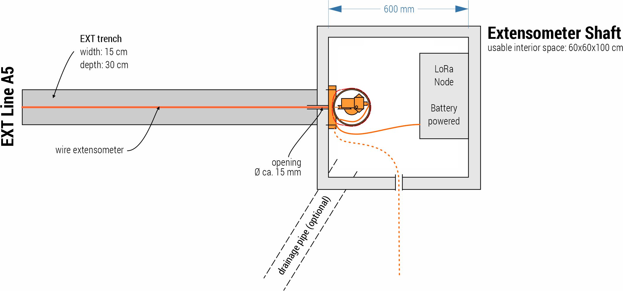
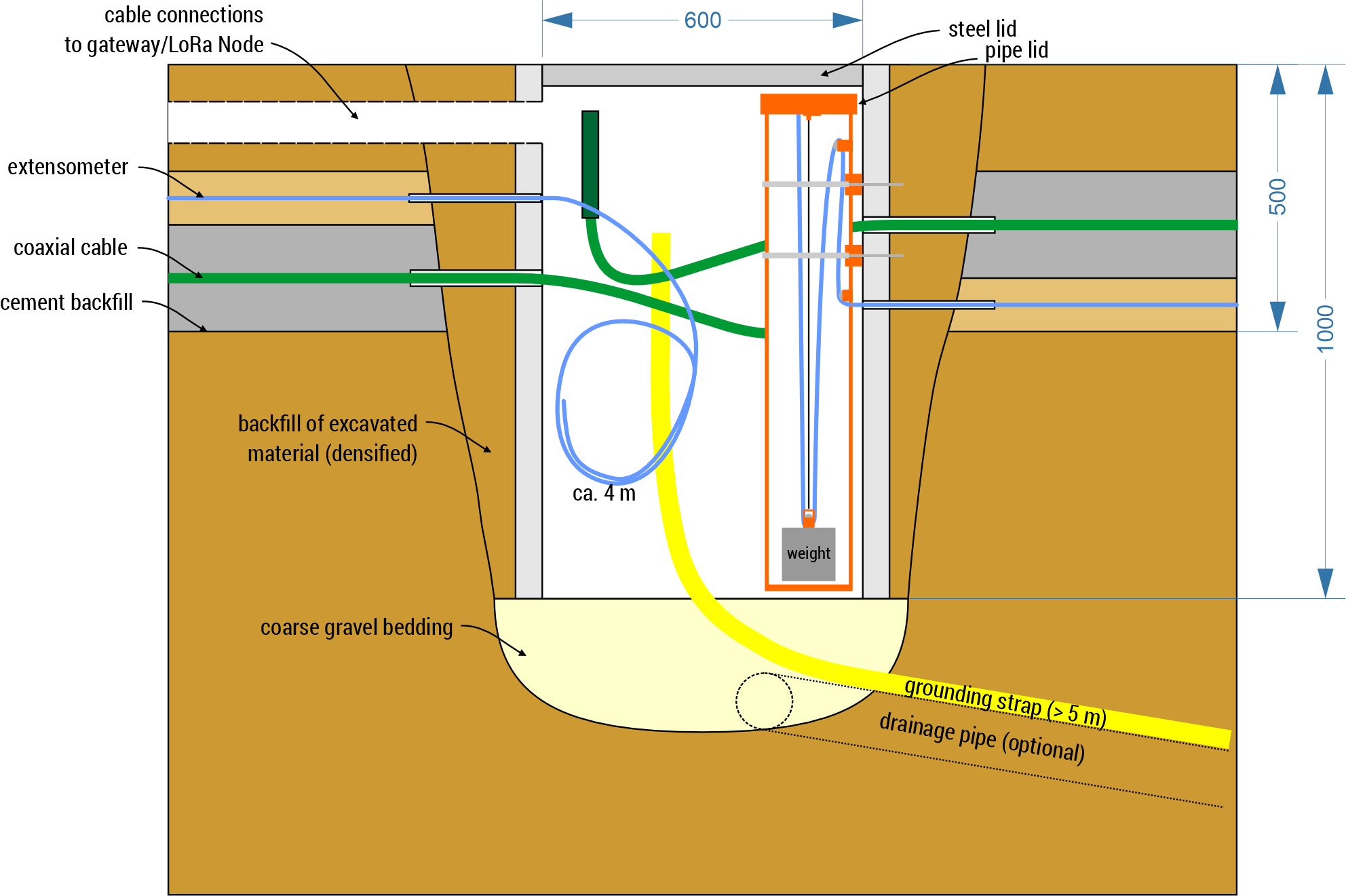
The concept can be applied to both vertical extensometers in boreholes as well as horizontal ones in trenches. No matter which of those is installed, a concrete shaft with minimum dimensions of 60x60x100 (LxWxD) is needed. This guide will not go into detail about the installation of extensometer cables, but only deal with the installation of the necessary infrastructure at both cable ends. In this manual, all material relations are marked bold. The following figures give an overview of the measurement concept for a horizontal extensometer measurement.
Materials
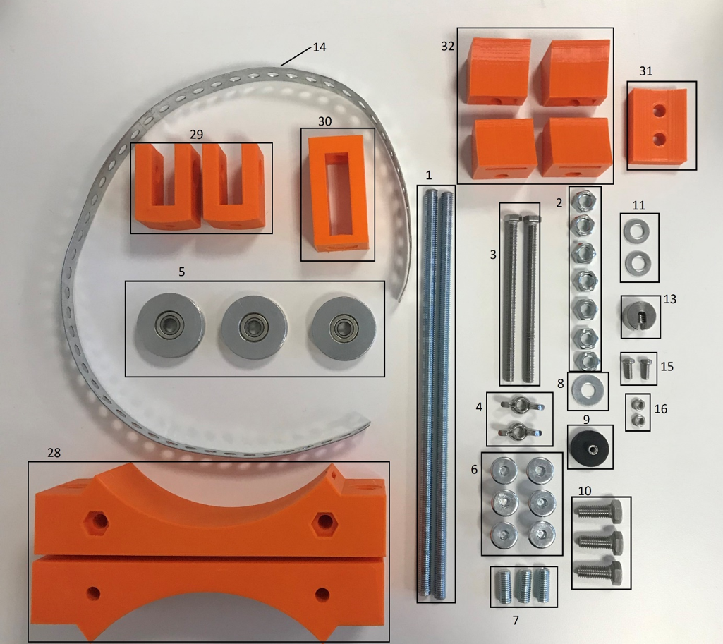
The Materials needed to construct a low-cost extensometer are listed below and shown in figure 1.
Table 1: General material list for the Low-Cost Extensometer.
| Nr. | Amount | Description |
|---|---|---|
| 1 | 2 | M8 Threaded rods 25 cm |
| 2 | 7 | M8 Nuts |
| 3 | 2 | M6 Screws 10 cm |
| 4 | 2 | M6 Wing nuts |
| 5 | 3 | Pulley |
| 6 | 6 | M8*11,5 Galvanized sleeve nut |
| 7 | 3 | M8 Set screws 2 cm with inner hexagon |
| 8 | 1 | Magnetic washers d=2 cm |
| 9 | 1 | Neodym Magnet d= 2cm, M4 inner thread |
| 10 | 3 | M8 Screws with hexagon, 2 cm |
| 11 | 2 | Washers d=1,5 cm |
| 12 | 2 | Cable ties |
| 13 | 1 | Rope clamp d=5 mm |
| 14 | 1 | Metal lashing strap 65 cm |
| 15 | 2 | M4*10mm Cylinder head screws |
| 16 | 2 | M4 Nuts |
| 17 | 1 | Sensor (Waycon) |
| 18 | 1 | Metal cylinder (d=12-15 cm, l= 10-20 cm, m=ca. 20kg) |
| 28 | 2 | EXT Pipe-Mount |
| 29 | 2 | EXT Pulley-Mount |
| 30 | 1 | EXT Weight-Mount |
| 31 | 1 | EXT Pully-Mount-Drilling-Template |
| 32 | 2 | EXT Pipe-Mount-Stretchers |
Tools and Parts
The necessary tools are only a standard array of screwdrivers, pliars, hexagon wrenches and so on. A professional drill with big (8-12 mm) concrete drill bits is necessary for attaching the parts to the shaft. Additionally, a big hammer can help in putting the threaded rods into the shaft walls.
Preparation of Weights
The weights should have in the center an 8 mm hole with a M8 thread to which the EXT Weight-Mount (Nr. 30) is attached using M8 screws with hexagon (Nr. 10), as well as a Pulley (Nr. 5).
3D Printed Parts
The necessary/useful 3D printing designs that we used in the test installation are to be found in the 3D prints section.
Installation
This section deals with the installation of the extensometer (sensor side) in the shaft. The steps are as follows:
- Pipe preparation
- Cut it so it just fits in the shaft (about 5 cm below the end)
- Drill a hole at the height at which the extensometer will enter the shaft and one hole below it with the drilling template (31). The pulley (5) and pulley mount (29) attach to the lower hole to guide the extensometer wire to the weight
- In case the extensometer wire enters the shaft at a very low level, the pulley needs to be above the entrance hole and guide the extensometer upwards \todo{draw concept drawing}, and another pulley needs to be attached at approximately 5 cm under the top of the pipe (see figure \ref{fig:assembly}d)
- Fix holder to the wall (28 EXT Pipe Mount) with dowels and M8 threaded rods which are cut to the appropriate size
- Tighten with M8 nuts
- Prepare the lid
- Drill two holes in the lid for the sensor which should be placed as indicated in the picture \todo{missing figure}
- Saw space for the cable in the lid and pipe (picture \todo{include figure})
- Insert cable
- Into upper hole
- Through the weight
- Through the lid
- Pipe preparation
- Lift pipe into shaft
- Attach to the bracket
- Lift weight (approx. 10 centimeters) and secure with rope stopper
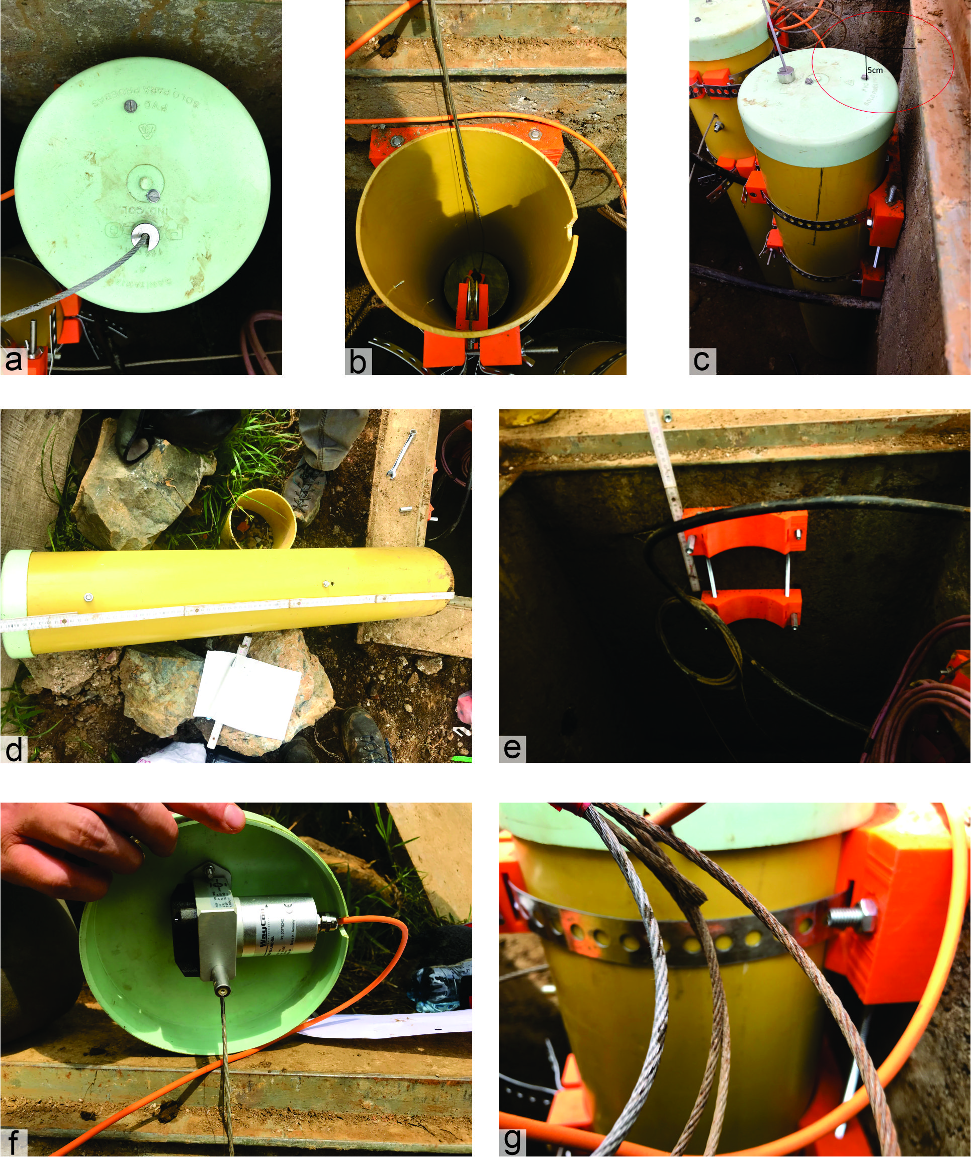
Explanation of figure: a) Lid with holes for the sensor and the extensometer wire. b) Inside of pipe with pulley, weight and cutout on the right. c) Finished pipe on the shaft wall with indication of the optimal height of the extensometer under the shaft lid. d) Prepared pipe with holes for pulley and extensometer wire. e) Preparation of EXT Pipe-Mount to the shaft wall f) Underside of the lid with the sensor attached and the sensor wire going through the cutout. g) Mounted pipe on the shaft wall.
Attaching Measurement Node to Sensor
For attaching the Waycon sensor to the measurement node, the wires from the sensor have to be attached to GND, power (12 V) and the analog port of the measurement node. The chosen analog port has then to be selected when programming the node for extensometer operation (see Software Installation for Measurement Nodes).


