Table of Contents
Software Installation for Measurement Nodes
Introduction and Overview
This document provides the necessary steps required for the installation and configuration of the Inform@Risk LoRa Nodes. The Inform@Risk LoRaBasis software requires only open-source libraries and dependencies to be installed in order to setup the LoRa nodes. For more information about the hardware on the PCB, please check the corresponding hardware documentation under www.informrisk.alpgeorisk.com. A short overview of the hardware is given in the subsequent section.
Hardware Overview
The circuit board needed for this software is called 'Inform@Risk PCB'. It consists of about 100 components, including a high quality analog-digital converter (ADS 1220), an accelerometer (ICM20948) and Thermometer as well as a Barometer (BMP388). The microprocessor used is an Arduino MKRWAN 1310, with an SAMD21 processor and Murata CMWX1ZZABZ LoRa chip.
Additionally, a high-quality inclination sensor (Murata SCL3300) can be added to the board and connected using a 6-pin connector. If a subsurface sensor is attached to the board, an additional accelerometer (BMA456) is connected.
Software Overview
- Various Arduino Libraries to be downloaded in the Arduino IDE:
- SPI.h (installation not needed)
- Libraries to be downloaded from the Inform@Risk GitHub page:
- AGR ADS1220 Library: edited by AlpGeorisk (agr_ads1220.h)
- Seeed Studio Step Counter/Bosch BMA456: edited by AlpGeorisk (arduino_bma456.h)
The SPI.h is a standard library that can be accessed by just including <SPI.h>. The library agr_ads1220.h is an adaptation of the standard 'adafruit ads1220' library. The arduino_ bma456.h is also an adaptation from the Seeed BMA456 Library.The modified source codes can be found in the 'Dependencies' folder.
Setup and Installation
Hardware Setup to Upload and Test the Nodes
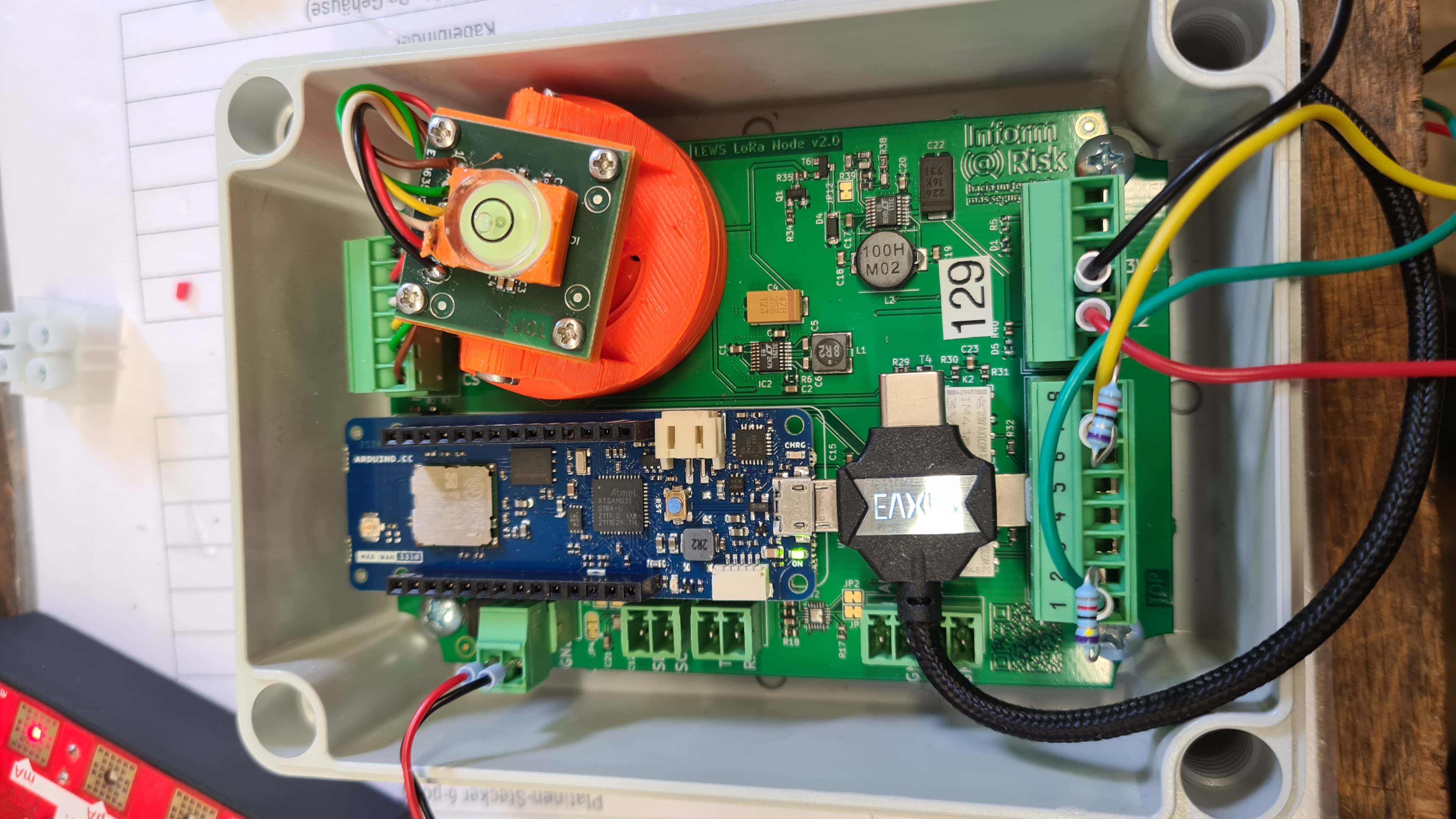
In order for the nodes to work, the PCB has to be prepared as shown in the LoRa Measurement Nodes section. A power supply, such as a battery or solar powered lid, or a power supply with 3.5-15~V is needed since the nodes can not be powered by USB any more after removing the connection (Step 6 in part 3.1 'Preparation of the PCB and bottom part'). Then, a micro-usb cable is used to connect the Arduino to a computer. Please note that this micro-usb cable needs to be able to transmit data (charging-only cables don't work!). Also, because of the tight space in the enclosure, an angled plug is convenient or even necessary. An example setup is shown in the subsequent figure.
Setting up Inform@Risk Software
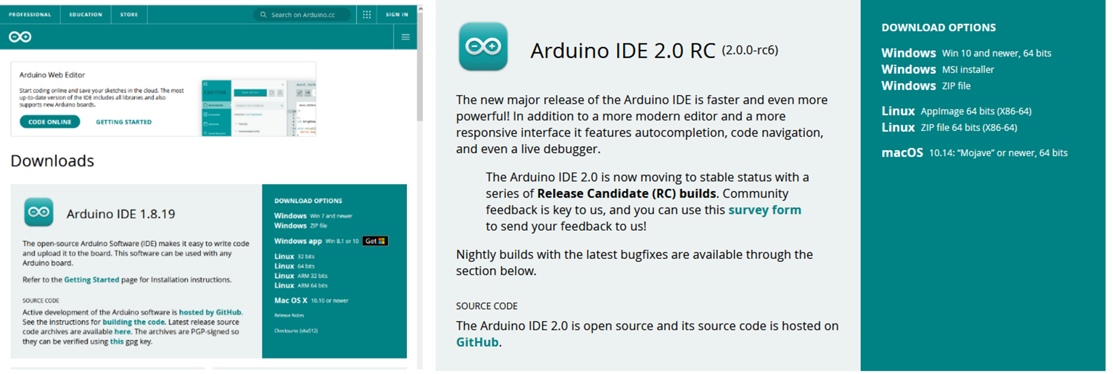
First, install the Arduino IDE from https://www.arduino.cc/en/software. Either the regular Arduino IDE or the newer Arduino IDE 2.0, which has updated editor functionality, can be used. The following screenshots are from the regular IDE, v. 1.8.19 (see following figure).
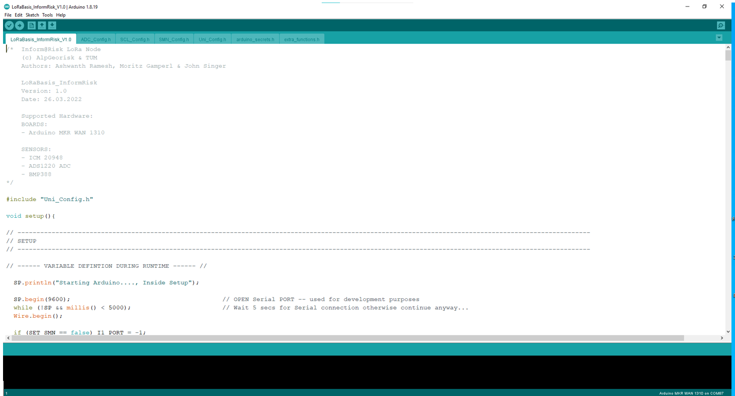
When the IDE is installed, open the file “LoRaBasis\textunderscore InformRisk\textunderscore VXX”, with XX representing the current version number. You will see a similar screen to the one below.
The tabs correspond to the ‘.h’ files in the folder in which the Arduino file is located. The .h files have different functions, which are explained below. If the Inform@Risk board is used, usually only the Uni_Config.h file needs to be changed by the user.
The tabs' functions are as follows:
| Name | Functionality |
|---|---|
| LoRaBasis_InformRisk | Main Code, which houses the main setup and loop functionality |
| setup.h | Configuration file for the Inform@Risk PCB |
| general_config.h | Universal configuration file: Stores universal parameters such as measurement and sleep time and sensor states |
| BATV_config.h | Configuration file for the battery voltage measurement |
| BARO_config.h | Configuration file for the barometric measurement |
| IMU_config.h | Configuration file for the IMU |
| AD24_config.h | Configuration file for the 24-bit ADC (Analog-Digital Converter) ADS1220 |
| AD12_config.h | Configuration file for the 12-bit ADC (Analog-Digital Converter) on the Arduino Board |
| INCL_config.h | Configuration file for the SCL3300 inclination board |
| SMN_config.h | Configuration file for the Subsurface Sensors on the Subsurface Measurement Node |
| arduino_secrets.h | Secret App EUI and Key which are stored on the gateway server for connection |
| extra_functions.h | Some additional functions which keep the code more readable |
When the libraries are installed correctly, the code should compile without problems. There are several issues that could occur, we will add possible problems in a future version of this guide. If you have problems, you can contact us under moritz.gamperl@tum.de.
Parameter Settings
setup.h
This file contains the setup for the Inform@Risk PCB. The settings here don't need to be changed by the user. Libraries that are necessary for the Arduino itself and its LoRa communication ('ArduinoLowPower.h', 'MKRWAN.h') and digital communication ('Wire.h') are included. Ports are setup and defined here too. If anything is changed on the PCB itself (e.g. different parts or port settings), the changes need to be applied here. All variables that are needed for the measurement loop and LoRa communication are defined here.
general_config.h
In this file, the basic settings can be changed by the user during installation. The general_config.h file is structured as follows:
- Timing setup
- Definitions of sleep mode
- Definitions of Data Packet Designator
Definition of Serial Port
The first line of code (# define SP Serial) defines which serial port is used. This is important for debugging, as the Serial monitor of the Arduino via USB shuts down once the processor goes into deepsleep-mode (described in detail in the deepsleep section). Hence, it is possible to change the serial output to the serial ports (RX, TX) on the PCB. This way, subsequent cycles after the first deepsleep command can also be read out from the serial port. If the serial ports on the PCB are used, the command needs to be changed to # define SP Serial1.
Definition of Sensor States
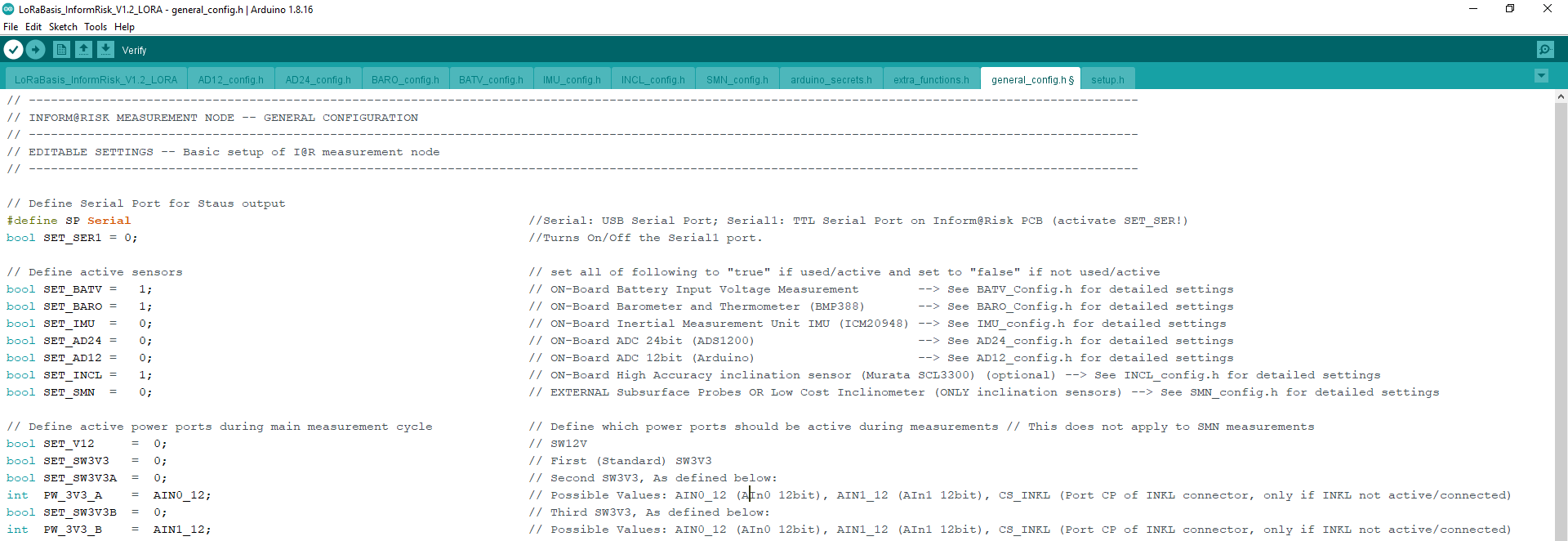
In this section of the general_config.h file, the sensor states are defined. This is used to turn on/off the different sensors which are connected on the board or can be attached to it. To turn a sensor on, simply write “= true” after the corresponding variable. This is the main section which needs to be changed when setting up a sensor either in the field or when preparing it beforehand. Please note that for the current PCB version (V 0.2), no IMU is attached on the board, so this is always false. The list of parameters can be seen in the next figure.
These settings can be seen as general toggles for the different sensors. If they are not turned on, all subsequent settings (for the ADC e.g. in the “ADC_Config.h” file) are disregarded. If, for example, the SMN is attached, but with settings different from the default (explained in the SMN section), the SMN must be turned on here and the specific settings have to be changed in the SMN\textunderscore Config.h file.
Definition of Active Power Ports
These parameters define which power ports should be active during measurements (does not apply to the SMN measurements). While the SET_V12 and SET_SW3V3 ports are the regular ports that can be accessed from the connectors on the PCB, the alternative SW3V3_A and SW3V3_B ports are actually the Analog in ports on the Arduino, which can be set to be used as outputs. They are different from the regular SW3V3 and V12 though, as they can supply less current than the latter.
Setup of LoRa Connection
Under this subsection of the general_config.h file, the parameters define the LoRa connection settings for data transmission. The parameters are listed in the next figure.
- The (# define LORA_BAND) defines the LoRa Band Connection. This is different for different countries. Please refer to the file for other options.
- The (# define LORA_ADR) defines the Automatic Data transfer Rate, where true allows the LoRa server to control the data rate, while false sets it to a fixed data transfer rate.
- # define LORA_DR also defines the data transfer rate according to the LoRa Band that is choosen. It varies according to different regions.
- # define LORA_CH_DEF defines the Channel Plan. True uses the default channels for the Band specified and false allows to use the channel specified in # define LORA_CH_ACT. See LoRaWAN Regional Parameters for Details.
- # define LORA_TIMEOUT defines the LoRa Connection timeout in seconds.
- The appEui and appKey are secret keys specified in the arduino_secrets_config.h file (described in detail in the corresponding section).
Timing setup
This subsection of the general_config.h file defines the timing parameters for loop intervals during measurement cycles. The parameters can be seen in the next figure.
loopintv controls the interval of one cycle, including initialization, measurement, data transmission, powerdown, sleeping and powerup. This means that the sleeptime itself is calculated each cycle by subtracting measlength, sensorstarttime and the rest of the calculation time from the total loopintv. extrafreq is not used for now (from V 1.0). The sleeptime is calculated as follows:
sleeptime = loopintv - (measlength + sensorstarttime)
Sleep Mode
This setting helps the sensors to go into sleep when the program is out of the measurement cycle. When #define SleepMode “deepsleep” is specified, most hardware is disabled (lowest power consumption). This setting is recommended for deployment of the LoRa nodes. When #define SleepMode “sleep” is specified, most of the hardware is disabled, but the COM is still active. #define SleepMode “nil” specifies all hardware to stay active.
Data Packet Designator
This defines the payload type, it is automatically updated depending on the sensors that are active.
ADC Settings and Measurement
The Analog to Digital Converter(ADC) sensor configuration is split into two major files:
AD12_config.h
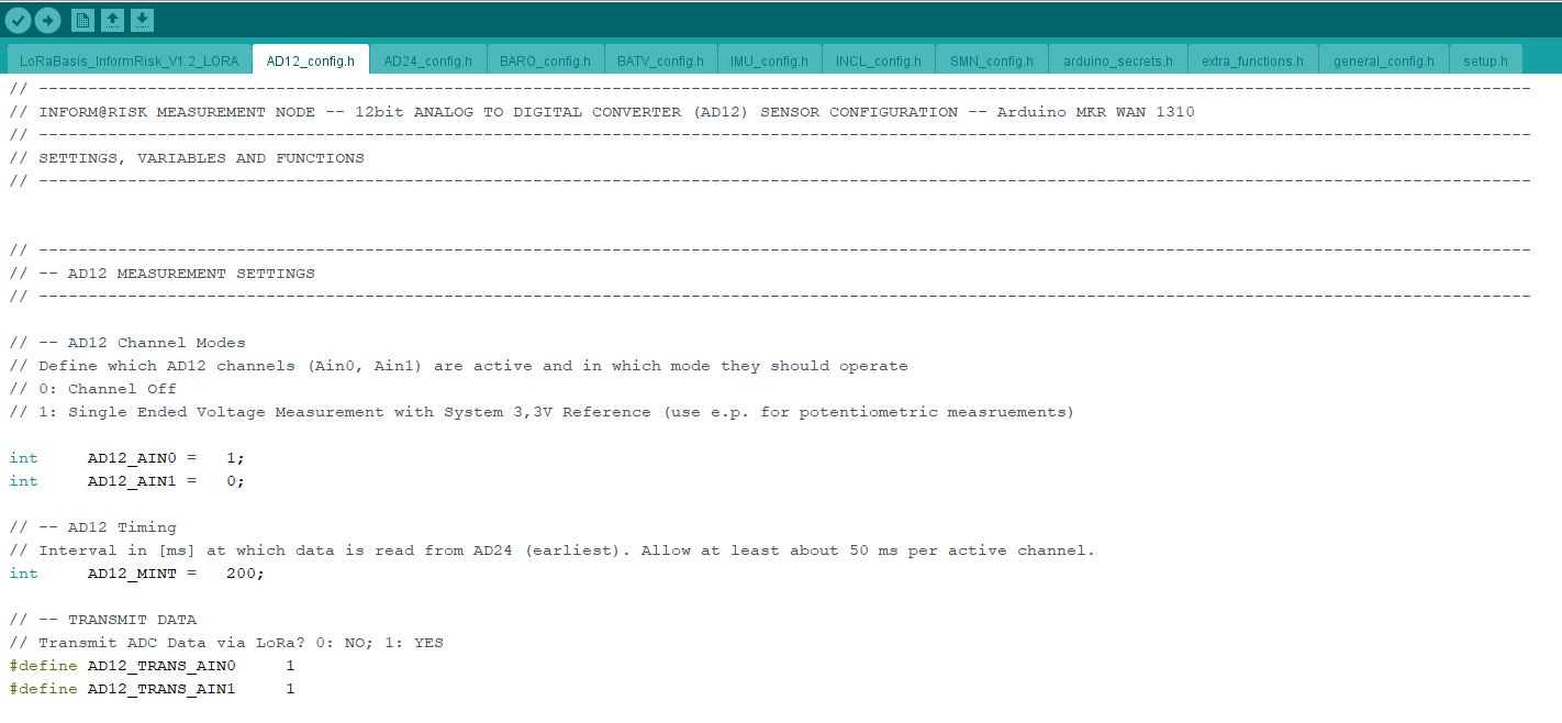
The 12-bit Analog to Digital Converter is embedded in the Ardunio MRKWAN 1310 board. The AD12_config.h file contains the settings for this sensor. The section under “MEASUREMENT SETTINGS” (refer to following figure) are the parameters that can be modified according to the sensor configuration.
- The # define AD12_AIN0 and int AD12_AIN1 define which AD12 channels are active, and in which mode they operate. The AIN0 and AIN1 are the two channels available. Setting either of the channels to 0 means the channel is off and setting it to 1 means the channel is set to a single ended voltage measurement with 3.3V reference.
- The int AD12_MINT defines the time interval (in ms) at which the AD24 measurement is read. It is advised to keep this setting above 50 ms per active channel.
- The #define AD12_TRANS_AIN0 and int AD12_TRANS_AIN1 defines whether the ADC data is transmitted via the LoRa network. O stands for no and 1 stands for yes.
The rest of the file contains Global variables and functions that must not be modified/edited.
AD24_config.h
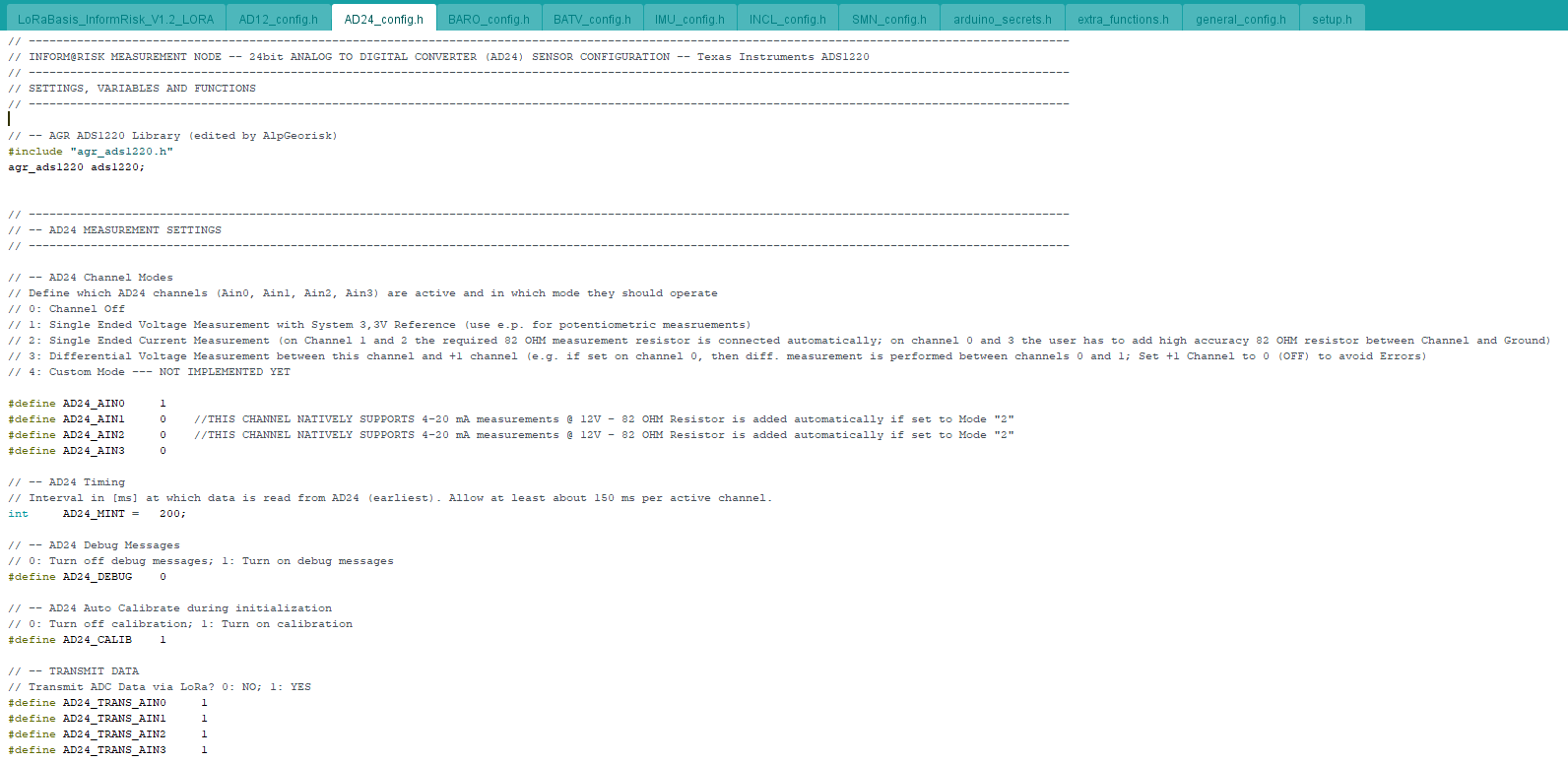
The 24-bit analog to digital converter is the ADS1220 (Texas Instruments). Hence the ADS1220 library must be added to the file. The AD24_config.h is quite similar to the AD12_config.h. The 24-bit ADC has 4 channels that can be set up. Each channel can also be set up in 5 different modes. Each mode has a detail explanation in the configuration file. It also has extra functionalities like calibration settings and debug message settings.
- The #define AD24_AIN0, AD24_AIN1, AD24_AIN2, AD24_AIN3 define which AD24 channels are active, and in which mode they operate. Setting any of the channels to 0 means the channel is off. Setting the channels to 1 means the channel is set to a single ended voltage measurement with 3.3V reference. Setting the channels to 2 means the channel has a single ended current measurement. Setting the channels to 3 means Differential Voltage Measurement between this channel and +1 channel (e.g. if set on channel 0, then diff. measurement is performed between channels 0 and 1. It is advised to set +1 Channel to 0 (OFF) to avoid Errors). Setting the channels to 4 means the channel is in Custom Mode (Not implemented yet)
- The int AD24_MINT defines the time interval (in ms) at which the AD24 measurement is read. It is advised to keep this setting above 150 ms per active channel.
- The #define AD24_DEBUG is used to activate debug messages. Setting it to 0 turns off the debug messages and setting it to 1 turns on the debug messages.
- The #define AD24_CALIB is used to activate auto calibration during initialization. Setting it to 0 turns off the calibration and setting it to 1 turns on the calibration.
- The #define AD24_TRANS_AIN0, AD24_TRANS_AIN1, AD24_TRANS_AIN2, AD24_TRANS_AIN3 defines whether the ADC transmit data via the LoRa network. O stands for no and 1 stands for yes.
SMN Settings and Measurement
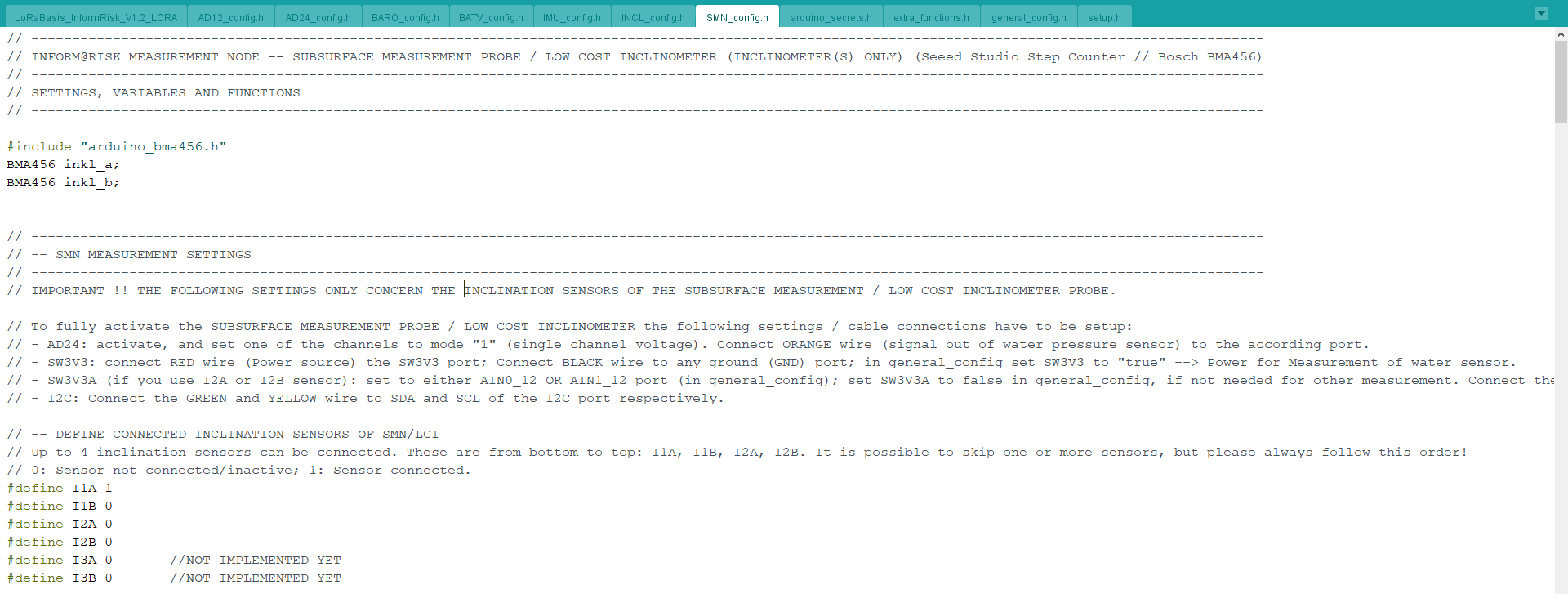
The Subsurface measurement probe/Low cost Inclinometer settings are defined in the SMN_config.h file. To fully activate the Subsurface Measurement Probe/Low Cost Inclinometer, a few settings/cable connections have to be set up as given below.
- The AD24 must be activated and one of the channels must be set to “mode 1” (single channel voltage). The wire for signal out of water pressure sensor (orsnge wire) to the appropriate port.
- Connect the power source (red wire) to the SW3V3 port, and ground it by connecting the black wire to the the GND port. Also change the SW3V3 parameter in the general_config.h to “true”.
- If the I2A or I2B sensor is used, set it to either the AIN0_12 OR AIN1_12 port in general_config.h (which is the correct port?). Set SW3V3A to false in the general_config.h, if it is not needed for any other measurements. Connect the brown wire to the appropriate port of the AD12 (4 pin output, not the AD24 8 pin output).
- Connect the green and yellow wire to the SDA and SCL of the I2C port respectively.
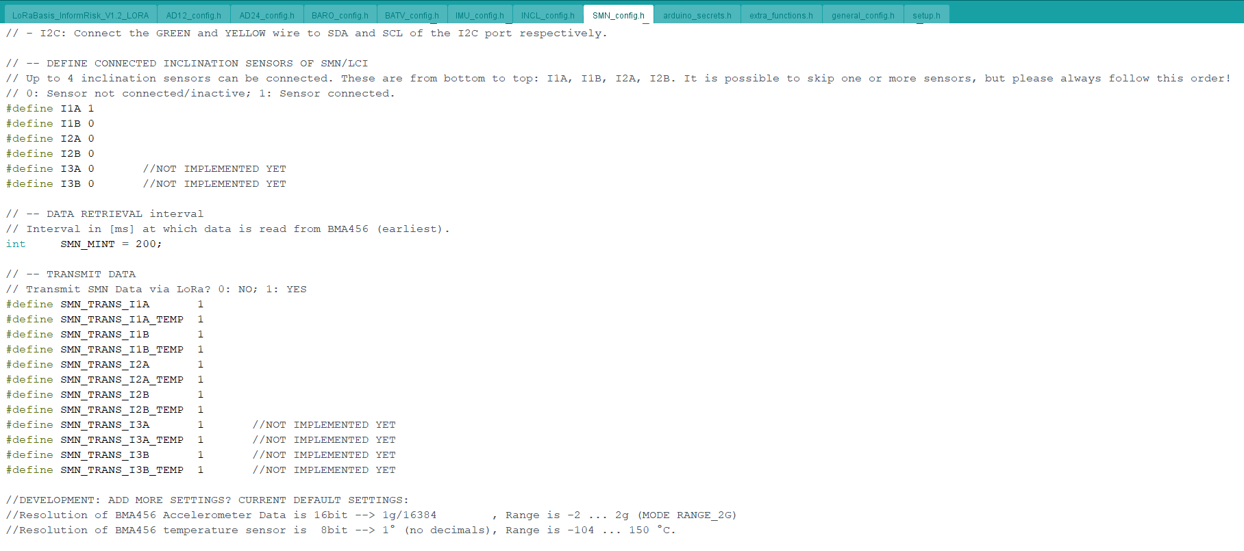
After follwing this procedure, the Subsurface Measurement Probe or Low Cost Inclinometer is set up. The following are the various parameters listed in the SMN_config.h that can be adjusted accordingly.
LCI Settings and Measurement
These are the settings that need to be changed by the user when installing a sensor. The subsequent tabs with configurations for the individual sensors on the other hand contain more detailed sensors that should only be changed when detail settings need to change. Each of these parameters is described in the code shortly on the right side as comments.
BATV_config.h
This file stores the configuration for the battery voltage measurement. The hardware is designed in such a way that it is possible to measure the battery voltage using the analog input of the Arduino. The settings do normally not have to be changed by the user.
BARO_config.h
In this section, the settings for the barometer BMP388 are defined. Usually, the settings don't need to be changed. The settings that could be changed by the user are, for example, BARO_MODE or BARO_TIMING. For more information on this, please check the BMP388 Library.
IMU_config.h
The IMU (short for 'inertial measurement unit') on the PCB is an ICM20948 by Invensense. Unfortunately, for the first version of the PCB for the Inform@Risk project, the sensor was not available, so the section is in the code, but it hasn't been tested yet. So, by default, the sensor is turned off in the current version of the code. In this file, various parameters as the hardware adress (#define ICM20948_ADDR), the data transmission (#define IMU_TRANS_ACC 1, #define IMU_TRANS_GYR 1, #define IMU_TRANS_MAG 1) and the measurement interval (IMU_MINT) can be changed. The rest are global variables which should not be changed by the user.
INCL_config.h
The INCL_config.h deals with the external SCL3300 inclinometer by muRata electronics which can be attached onto the PCB using a 3D printed file. This sensor is optional if the previously mentioned ICM is used, as it offers higher precision in its measurements, but is also more expensive. The parameters of the SCL that can be changed in the 'INCL_config.h' file are the inclination mode (INCL_MODE, four modes which vary in sensitivity), the temperature measurement (INCL_TEMP, can be turned on and off), fast read mode (INCL_FASTREAD, can be turned on and off; off by default), and transmit data for tilt and temperature (INCL_TRANS_TILT, INCL_TRANS_TEMP, on by default). The rest are variables and the measurement functions which should not be changed.
arduino_secrets.h
The arduino_secrets.h file holds the respective SECRET_APP_EUI and SECRET_APP_KEY which are set for the sensor on the gateway. For more on this, please also refer to the LoRa Gateway section.
extra_functions.h
In the extra_functions.h file, various additional and extraneous functions are compiled. For example, the DeepSleepMode() function performs the sleep functionality of the node, depending on what is set in the setup.h file. Also, functions on the ports setup (void PortsActivate(), void PortsDeactivate()) and various functions dealing with the data packets (void Payload_U32(), void Payload_I32(), void Packet10_B0_Prepare() and so on) can be found here.

