This is an old revision of the document!
Table of Contents
Inform@Risk Wiki
Documentation for a Landslide Early Warning System designed for informal settlements
Overview
Introduction
This website is part of the project Inform@Risk, which produced a blueprint for an integrated landslide early warning system for informal settlements. This wiki provide information about how a measurement systen for such an application can look, as well as instructions on how such a system can be reproduced. For now, the Wiki is available in English and Spanish.
This page first provides an overview of the measurement system as well as the other instructional documents. In the following section, the structure of the instructional documents is explained. In the subsequent section, social aspects are mentioned which are at least as important as the technical sections before. At the end, all resources and publications are enumerated in a list which also is valid for the other instructional documents.
All information is shared on the project website and this wiki. Feel free to contact us with comments, questions and general messages about the system. You can reach us under: moritz.gamperl@tum.de or singer@alpgeorisk.de.
Basic Concepts of the Measurement System
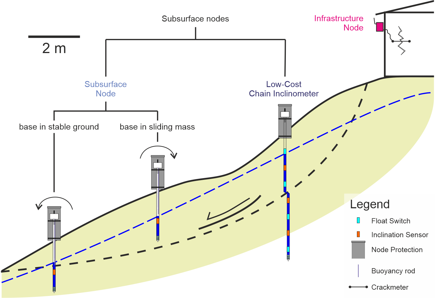
All sensors in the system are based on one basic measurement node design, to which additional sensors can be attached easily. This way, the system can be very versatile while keeping the cost low. The basic measurement node can simply be attached to walls to measure inclination or e.g. crack elongation with an external crackmeter (figure \ref{fig:meascon}). In this case, we call it 'Infrastructure Node'. When subsurface sensors are attached to it, we call it 'Subsurface Node' or Low-Cost Inclinometer', depending on the drilling depth and according number of sensors attached.
The Low-Cost Extensometer on the other hand can be used to measure elongation along an axis, be it vertically (e.g. in a borehole) or horizontally (e.g. across a slope). It consists of the measurement wire, the measurement tools in a shaft and a potentiometric sensor. The latter is then attached to the ADC (Analog-Digital Converter) of the measurement node.
All measurement nodes should be connected to at least two LoRa gateways, which should ideally be located in safe spots, with as good as possible line of sight to all sensors. There is also an instructional manual for the LoRa gateway, but it is more general in comparison to the other manuals. This is because the gateway will be very specific to the site and not as versatile as the individual sensors. Still, the manual contains the general overview of what is needed. If you have questions about this, don't hesitate to contact us.
The integration of the sensors into public space is very important, especially in urbanized regions, because it can improve the acceptance of the system by the local population. As part of the social component, it is further addressed in section \ref{c:soc}.
Structure of provided Materials
In order to make reproduction of the system as easy as possible, several files and documents are published on the project website and this wiki: project website. The can be divided into instruction manuals, datasheets and 3D printing files. All software is published on the project's GitHub page.
In the following sections, all documents are listed and explained whenever necessary.
Instruction Manuals
We created several instruction manuals. It starts with an overview of the system and the basic measurement node, which is needed for all other measurements. Then the attachments (Subsurface Probe and Low-Cost Inclinometer) are addressed. The Low-Cost Extensometer is last since it is based on a slightly different approach. They are listed in the following (clicking on the headlines directly leads you to the respective wiki page):
- Overview
Overview and general concepts. - Measurement Nodes Assembly
Assembly of basic measurement nodes: PCB and 3D prints. - Software Installation
Necessary steps for installing the software of the measurement nodes are explained. - Subsurface Probes
Assembly and installation of subsurface probes, which extend about 1-2 m into the subsurface. - Low-Cost Inclinometer
Assembly and installation of Low-Cost Inclinometer, which extend about 3-6 m into the subsurface. - Low-Cost Extensometer
Assembly and installation of the horizontal and vertical Low-Cost Extensometer.
Datasheets
For some parts of the system, datasheets were produced. Like the instructional documents, they can be downloaded from the project website. Third-Party datasheets for the sensors and some of the components that were used are referenced in the respective instructional documents.
3D Printing Files
3D printing files are supplied for the measurement node, the Subsurface Probes (they are identical to the ones needed for the Low-Cost Inclinometer) and the Low-Cost Extensometer. They are sorted in this way on the website. Here, a short overview is given. Detailed instructions can be found in the individual instruction manuals.

